
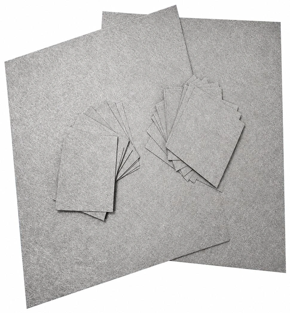
Application and Selection.
Sintered fibres form a permeable structure with space for retained contaminants. Select retention, permeability and structural backing for the finished filter.
- Media families
- A3 · C4 · C3 · D4 · E4 · B3 · F3
- Sheet size
- Listed catalogue size: 1500 × 1180 mm
- Construction
- Pleatable or non pleatable, by media family
Permeability and bubble point comparisons require matching test conditions. Confirm the airflow unit, test pressure and media construction.
Technical Information
Open a section to view the details, tables and illustrations.
Construction & Family Selection
A Fibre Network with Space for Contaminants
In graded depth media, coarser inlet regions intercept larger contaminants while finer regions retain smaller material within the structure. Distributing retention through the depth helps use the available pore volume.
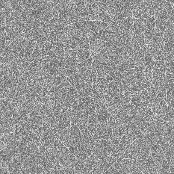
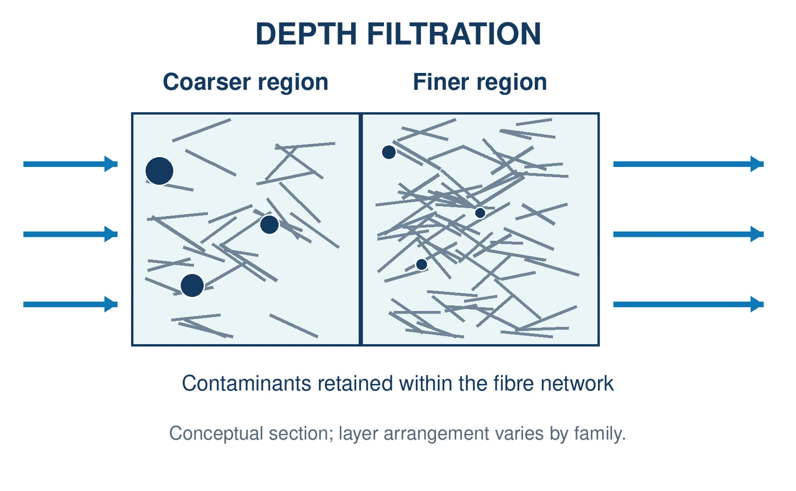
Fibre close up and explanatory depth filtration schematic
Family | Construction | Catalogue Positioning |
|---|---|---|
A3 | Multilayer; pleatable | Polymerisation and spinning |
C4 | Multilayer; pleatable | Compression resistance and dirt capacity |
C3 | Multilayer; pleatable | Monomers and lower - viscosity fluids |
D4 | Multilayer; non - pleatable | High strength polymer leaf discs |
E4 | Symmetrical multilayer | Improved pleating behaviour |
B3 | Single layer; pleatable | Low viscosity, low - contamination liquids |
F3 | Single layer; pleatable | Economical, lightweight media |
Listed sheet size: 1500 × 1180 mm. Protective mesh is offered on one or both sides.
Match the Construction
The diagram illustrates a graded medium. Confirm the actual layer sequence, flow direction, protective mesh and structural backing for the selected family.
A3 - Polymerisation & Spinning
Multilayer Media for Pleated Filters
A3 is the broad pleatable family in the catalogue, covering polymerisation, spinning and process liquid applications.
Model | AVG. BUBBLE POINT Pa | Porosity % | AIR PERMEABILITY* L/(dm²·min) |
|---|---|---|---|
3A3 | 12300 | 67 | 10 |
5A3 | 7600 | 80 | 34 |
7A3 | 5045 | 74 | 62 |
10A3 | 3700 | 78 | 108 |
15A3 | 2470 | 80 | 180 |
20A3 | 1850 | 82 | 265 |
25A3 | 1480 | 79 | 325 |
30A3 | 1235 | 79 | 450 |
40A3 | 925 | 76 | 620 |
60A3 | 630 | 86 | 1350 |
75A3 | 480 | 84 | 1470 |
80A3 | 450 | 85 | 1510 |
90A3 | 410 | 88 | 1740 |
100A3 | 360 | 89 | 2020 |
* Confirm units, test conditions and acceptance tolerances; see “Understanding the Test Data”.
Specify the Finished Filter
Confirm the media thickness, steel grade, supporting layers and effective filtration area before choosing a finished candle or pack assembly. A media code alone does not define the complete filter.
Retention Requirement
Request the particle size, removal efficiency and test method associated with the selected model. The numerical prefix in a model name is not presented here as an absolute micron rating.
C4 & C3 - Depth Filtration Media
Select for the Fluid and Mechanical Duty
C4 - Compression Resistant Media
Multilayer, pleatable construction aimed at dirt capacity and compression resistance.
Model | AVG. BUBBLE POINT Pa | Porosity % | AIR PERMEABILITY* L/(dm²·min) |
|---|---|---|---|
5C4 | 7400 | 73 | 32 |
7C4 | 5100 | 73 | 54 |
10C4 | 3700 | 73 | 75 |
15C4 | 2400 | 73 | 180 |
20C4 | 1850 | 73 | 230 |
25C4 | 1500 | 73 | 294 |
C3 - Lower Viscosity Fluids
Multilayer, pleatable media for monomers, prepolymers and other lower viscosity fluids.
Model | AVG. BUBBLE POINT Pa | Porosity % | AIR PERMEABILITY* L/(dm²·min) |
|---|---|---|---|
5C3 | 7100 | 86 | 37 |
10C3 | 3500 | 85 | 110 |
15C3 | 2400 | 85 | 203 |
20C3 | 1700 | 86 | 345 |
25C3 | 1700 | 86 | 385 |
30C3 | 1230 | 86 | 650 |
40C3 | 1036 | 86 | 675 |
* Confirm units, test conditions and acceptance tolerances; see “Understanding the Test Data”. The source lists 1700 Pa for both 20C3 and 25C3; these entries are retained as published.
Mechanical Duty
Bubble point pressure is a wetting test result. It is not the allowable operating pressure or the collapse differential pressure of the completed element.
D4 & E4 - Disc and Pleated Media
Choose the Required Forming Behaviour
D4 - High Strength Disc Media
Multilayer media for polymer leaf disc filtration; specified as non pleatable.
Model | AVERAGE BUBBLE POINT Pa | Porosity % | AIR PERMEABILITY* L/(dm²·min) |
|---|---|---|---|
2D4 | 18000 | 51 | 3 |
3D4 | 12300 | 72 | 13 |
5D4 | 7700 | 72 | 24 |
7D4 | 5000 | 72 | 43 |
10D4 | 4020 | 72 | 53 |
12D4 | 3200 | 72 | 85 |
15D4 | 2410 | 72 | 135 |
20D4 | 1900 | 72 | 165 |
25D4 | 1480 | 71 | 260 |
30D4 | 1230 | 75 | 350 |
40D4 | 925 | 75 | 625 |
E4 - Media for Pleating
Symmetrical multilayer construction developed for improved pleat formation.
Model | AVERAGE BUBBLE POINT Pa | Porosity % | AIR PERMEABILITY* L/(dm²·min) |
|---|---|---|---|
3E4 | 11500 | 70 | 10 |
5E4 | 8000 | 81 | 36 |
7E4 | 5300 | 68 | 40 |
10E4 | 3700 | 74 | 75 |
15E4 | 2466 | 71 | 132 |
20E4 | 1850 | 71 | 220 |
*Confirm units, test conditions and acceptance tolerances; see “Understanding the Test Data”.
B3 & F3 - Single Layer Media
Options for Different Service Priorities
B3 - Low Contamination Liquids
Pleatable media for lower viscosity liquids such as hydraulic oil and fuel.
Model | AVERAGE BUBBLE POINT Pa | Porosity % | AIR PERMEABILITY* L/(dm²·min) |
|---|---|---|---|
5B3 | 7000 | 79 | 45 |
10B3 | 3700 | 81 | 125 |
15B3 | 2470 | 78 | 250 |
20B3 | 1850 | 80 | 400 |
40B3 | 925 | 84 | 1100 |
60B3 | 530 | 74 | 1660 |
F3 — Economical Media
Lightweight, pleatable construction positioned as an economical option.
Model | AVERAGE BUBBLE POINT Pa | Porosity % | AIR PERMEABILITY* L/(dm²·min) |
|---|---|---|---|
10F3 | 3500 | 71 | 90 |
15F3 | 2600 | 77 | 140 |
20F3 | 1800 | 70 | 240 |
40F3 | 925 | 71 | 625 |
60F3 | 550 | 71 | 1200 |
* Confirm units, test conditions and acceptance tolerances; see “Understanding the Test Data”.
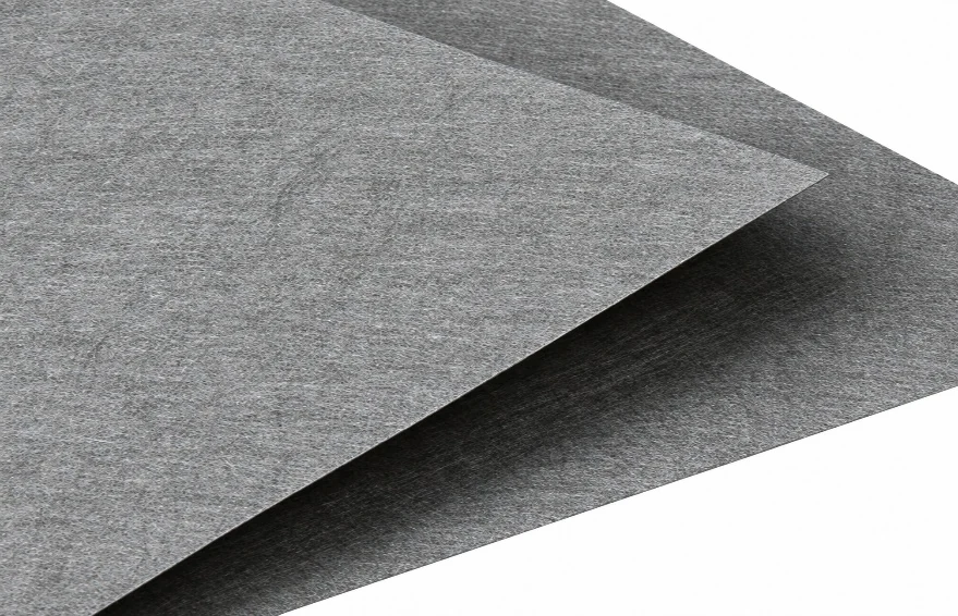
Representative sheet surface and edge detail
Understanding the Test Data
Compare Values on a Defined Test Basis
Average Bubble Point Pressure. This is the label used in the catalogue. In a wet bubble point test, gas displaces the wetting liquid from pores. The result depends on the liquid and procedure; establish the defined endpoint before comparing suppliers.
Porosity. Porosity is the fraction of void space in the medium. It differs from particle removal efficiency, woven mesh open area and the effective area of a pleated filter.
Air Permeability. The catalogue reports a flow per unit area. A meaningful comparison requires the test pressure difference, gas conditions and specimen construction. These conditions must be confirmed for the selected media
Unit Clarification
The catalogue prints the airflow unit as “I/dm².min”. This guide interprets it as L/(dm²·min), meaning litres per square decimetre per minute. Confirm the unit and test pressure with the supplier.
What the Tables Do Not Define
The page does not provide complete grade specific thicknesses, alloy specifications, retention efficiency curves or finished element pressure and temperature limits. Obtain these for the selected construction before approval.
From Media Data to Process Performance
Pressure loss depends on fluid viscosity, flow, filtration area and media resistance. Airflow figures cannot directly predict polymer melt pressure loss.
Use application specific flow data and include the support structure and element geometry in the review.
Controlled Comparison
Compare candidate media at the same fluid, temperature, throughput and required retention. Verify clean pressure loss and subsequent pressure rise in the actual supported element.
Application, Cleaning & Validation
Qualify the Media in the Operating Process
Metal fibre media are used in polymer candle, leaf disc and spin pack filters. Removing solids, agglomerates and gels can support filament continuity and film quality; actual performance depends on the contamination and selected medium.
Define the Process. Record polymer or fluid grade, viscosity basis, flow range and temperature. Identify contamination type, current element reference and the reason for replacement or improvement.
Review the Assembly. Provide a drawing with active area, media stack, supports, flow direction, seals and end connections. Include operating pressure, change out differential pressure and transient conditions.
Set Trial Acceptance. Record initial pressure loss, pressure rise per operating hour or tonne, run duration and product quality. In spinning, include spinneret blockage and filament break trends; in film, track the agreed defect measure.
Cleaning and Reuse
Select the cleaning method for the deposit, alloy and assembled filter. Polymer filters may require thermal, chemical or ultrasonic treatment, followed by cleanliness and integrity assessment. Use a qualified procedure matched to the element
Compare post cleaning flow and integrity results with a documented new element baseline. Integrity testing and particle removal efficiency measure different things; an acceptance method needs validation for the particular medium and element design.
RELEASE FOR REUSE Set approved acceptance limits, retain the element identification and cleaning history, and inspect the support structure, joints and sealing surfaces before returning the filter to service.
Release for Reuse
Set approved acceptance limits, retain the element identification and cleaning history, and inspect the support structure, joints and sealing surfaces before returning the filter to service.
Supply Information
Specify the model, alloy, thickness, dimensions, mesh protection, final element drawing, quantity, required documentation and trial approval criteria. Include expected annual consumption and the requested delivery schedule.
Prepare Your Enquiry
What to Send Us.
Media family or existing reference; polymer or liquid; temperature; throughput; retention target; flow resistance test basis; support layers.
Discuss this product