Application and Selection.
The capillary design, material and plate interface are selected together. Final filament properties also depend on polymer, filtration, metering, quenching and drawing conditions.
- Plate forms
- Circular, annular, rectangular and custom
- Capillaries
- Round, profiled and application specific layouts
- Inspection
- Geometry, finish and hole to hole consistency
Technical Information
Open a section to view the details, tables and illustrations.
Precision Capillary Plates for Controlled Filament Formation
The spinneret forms the final flow passages before polymer melt or solution becomes individual filaments. Geometry must be matched to the material, spinning route, throughput per hole, quench field and required product.
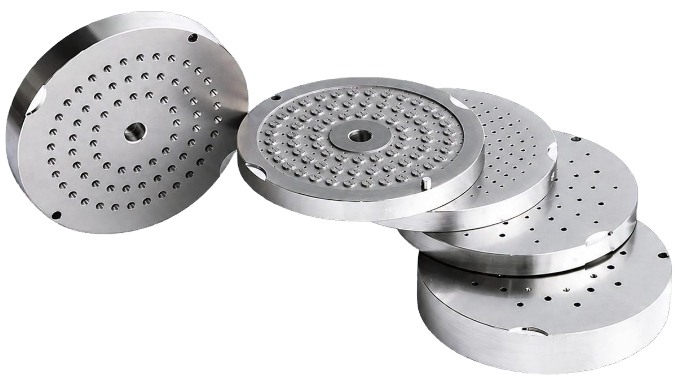
Representative round spinneret plates; final geometry is drawing specific
Application Scope
Product Duty | Typical Review Focus |
|---|---|
POY & FDY Filament | Hole to hole flow consistency, plate pattern, quench exposure and target Linear Density. |
BCF & Industrial Yarn | Throughput, filament profile, pressure stability and robust cleaning practice. |
Staple Fibre | High hole count, distribution across the active area and repeatable capillary condition. |
Monofilament & Specialty | Application specific diameter or profile, material compatibility and surface finish. |
Custom Component
A spinneret is released from a verified drawing or qualified sample together with the agreed process and inspection basis.
From Metered Polymer to Multiple Filament Streams
The spinneret is the final precision element in the spin pack. It does not work alone: melt or solution preparation, filtration, metering, temperature, quench and downstream draw all contribute to the result.
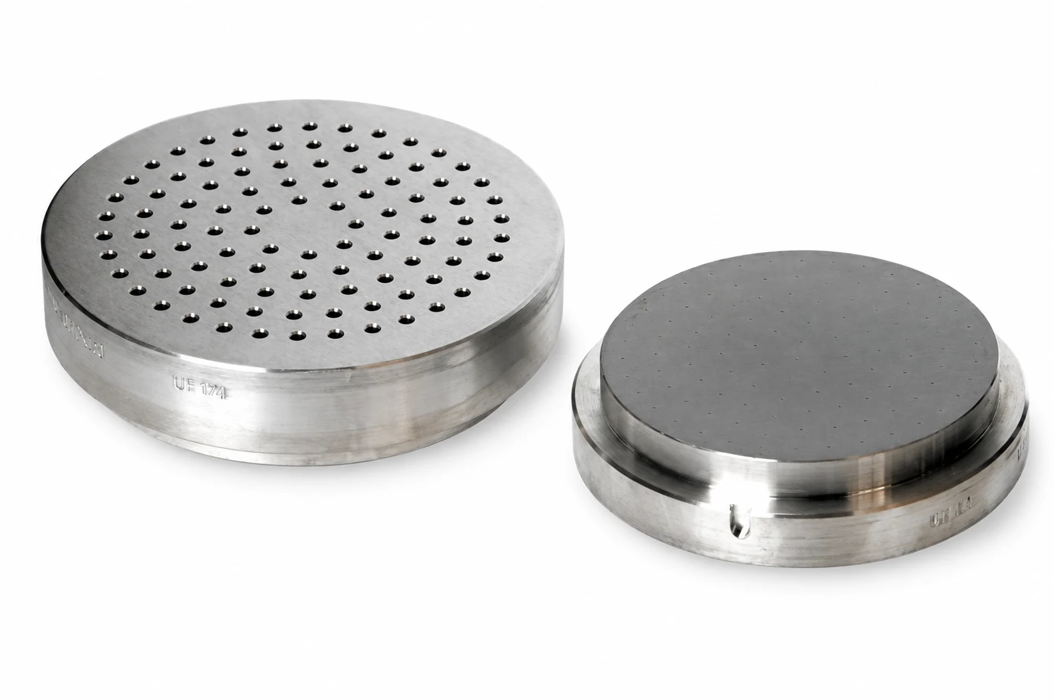
Representative capillary plate assemblies
01 DEFINE THE FINAL PASSAGE: Each capillary establishes the last controlled geometry through which the polymer flows.
02 CREATE THE FILAMENT ARRAY: Hole count, pitch and layout establish the number and spatial distribution of emerging filaments.
03 SUPPORT REPEATABILITY: Consistent capillary dimensions, clean transitions and an undamaged exit face help filaments emerge under comparable conditions.
System Boundary
Final filament properties must be qualified on the complete spinning line; spinneret geometry is one controlled input within that system.
Design Variables
A Complete Drawing Controls More than Hole Diameter
The capillary and plate should be specified as one functional interface. Small changes can alter pressure, shear history, residence behaviour, extrudate swell, cleanability and quench interaction.
01 CAPILLARY PROFILE: Round, trilobal, multilobal, hollow, slot or another defined cross section.
02 DIAMETER / SLIT WIDTH: Selected with polymer rheology, throughput per hole, drawdown and target filament size.
03 CAPILLARY LENGTH AND L/D: Affects pressure loss, flow development, elastic recovery and cleaning access.
04 ENTRY AND TRANSITION: Counterbore, countersink and land transition guide polymer into the final passage.
05 HOLE COUNT AND ARRANGEMENT: Concentric, square, diamond, linear or partitioned layouts coordinate filament count and quench field.
06 PLATE AND SEALING INTERFACE: Outside form, thickness, locating features, seating face and orientation must match the pack and beam.
Drawing Priority
Dimensions, datum structure, inspection method and acceptance criteria must be agreed together; a nominal hole size alone is not a complete spinneret specification.
Spinning Routes
Process Route Changes the Spinneret Requirement
Feed state, solidification mechanism, chemistry and hole count differ between melt, dry, wet and dry jet wet spinning. Material and geometry must therefore be reviewed for the actual line.
Route | Feed and Solidification | Design Emphasis |
|---|---|---|
Melt Spinning | Molten polymer extruded and solidified by cooling in air, water or another cooling medium. | Polymer rheology, temperature, capillary flow, die swell, quench pattern and throughput per hole. |
Dry Spinning | Polymer solution extruded into heated gas while solvent is removed. | Solution compatibility, transition quality, hole profile, residence behaviour and solvent service material selection. |
Wet Spinning | Polymer solution extruded directly into a coagulation bath. | High hole count, bath compatibility, jet stability, plate layout and corrosion resistant metallurgy where required. |
Dry Jet Wet / Air Gap | Solution passes through an air gap before entering the coagulation bath. | Uniform capillaries, jet path, air gap stability, plate alignment and controlled solution delivery. |
Representative Polymer Families
Route | Examples |
|---|---|
Melt | Polyester, polyamide, polypropylene, polyurethane and other melt spinnable polymers. |
Dry | Acetate, acrylic, elastomeric and other compatible solution spun systems. |
Wet / Air Gap | Rayon, acrylic, PAN precursor, aramid and other coagulation spun systems. |
Compatibility Check
Polymer or solution composition, additives, temperature, pressure, solvent/coagulant exposure and cleaning chemistry govern the final material and finish.
Filament Geometry
Capillary Profile Establishes the Nominal Cross Section
Profiled holes can create optical, tactile, transport, bulk or functional effects. The final fibre profile is not a simple one to one copy of the hole because rheology, swell, drawdown, quench and solidification modify the emerging stream.
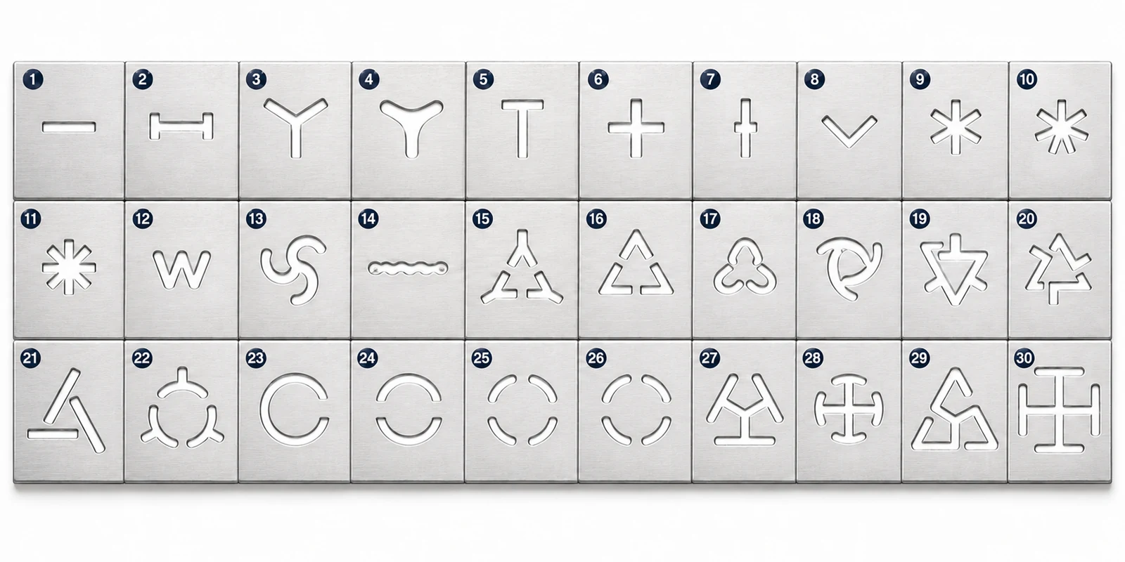
Representative capillary profiles
Profile Family | Typical Design Objective |
|---|---|
Round | General textile, industrial, staple and monofilament duties. |
Tri lobal / Multi lobal | Modified lustre, cover, bulk, capillary channels or optical effects. |
Hollow / Segmented | Lower apparent density, insulation, bulk or fluid transport functionality. |
Flat / Ribbon / Slot | Surface area, flexural response, reflectance or application specific geometry. |
Complex / Multicomponent | Sheath core, side by side, islands in sea or other engineered structures requiring matched polymer paths. |
Profile Qualification
Approve both the spinneret dimensions and the achieved filament cross section under the intended throughput, temperature, quench and draw conditions.
Capillary Flow
Geometry, Polymer Rheology & Throughput Must Be Determined Together
The same capillary can behave differently when viscosity, temperature, degradation state or throughput changes. Technical selection should therefore use process data rather than catalogue geometry alone.
Input | Primary Process Effect | Qualification Question |
|---|---|---|
Diameter / Flow Area | Changes average velocity, shear and pressure requirement at a given throughput. | Can the target mass flow per hole be achieved within the approved pressure window? |
Capillary Length / L/D | Changes pressure loss and the degree of flow development before the exit. | Does the profile remain stable and cleanable for the selected polymer? |
Entry Transition | Influences acceleration, local shear and potential stagnation at the passage entrance. | Is the transition smooth, concentric and reproducible across the plate? |
Polymer Viscosity | Changes pressure, shear stress, swell and sensitivity to temperature or residence time. | Which viscosity, IV/MFI or solution concentration basis governs the design? |
Throughput Per Hole | Directly changes mass flow, jet velocity and downstream attenuation demand. | Is throughput defined per pack and per active capillary? |
Temperature | Changes viscosity, relaxation and degradation risk. | Are normal, start up and maximum temperatures documented? |
Linear Density Relationship
Final linear density is primarily a mass throughput and take up relationship.
Capillary diameter influences flow and spinnability, but must not be treated as a standalone predictor of final linear density.
Profile Retention
For hollow or complex sections, die swell and solidification can alter profile degree; validate the actual filament rather than relying only on the machined outline.
Precision and Inspection
Hole to Hole Consistency Protects Repeatable Spinning
Inspection should confirm the complete capillary, not only the visible outlet. Burrs, deposits, wear, distortion or partial blockage can change an individual stream even when the plate still fits the machine.
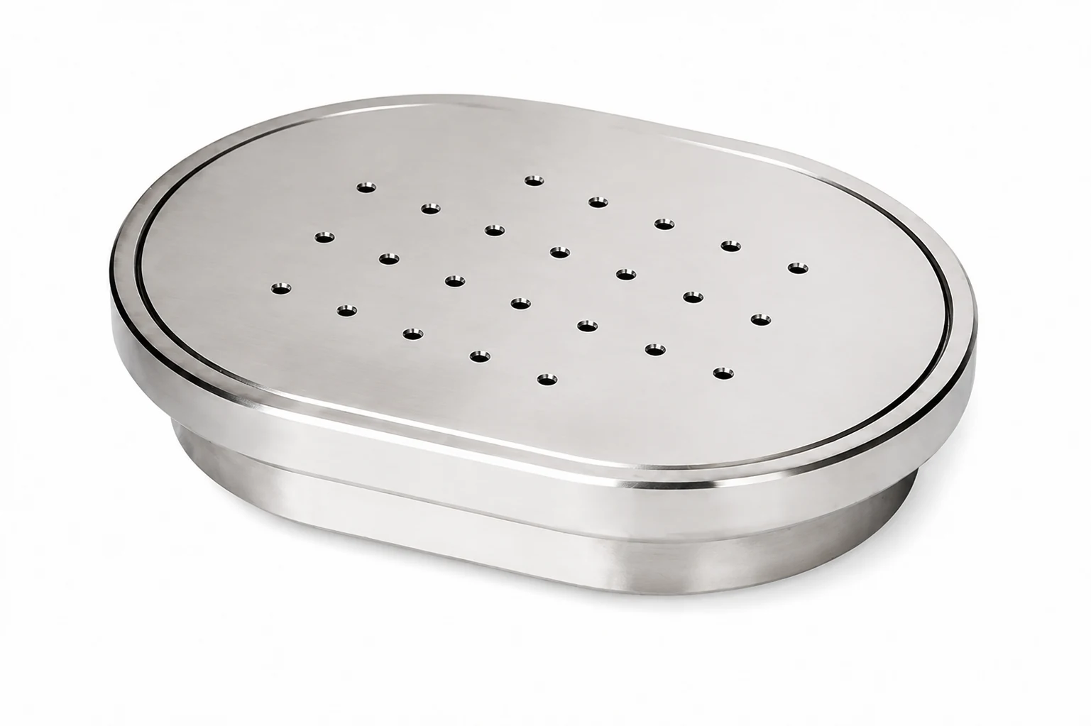
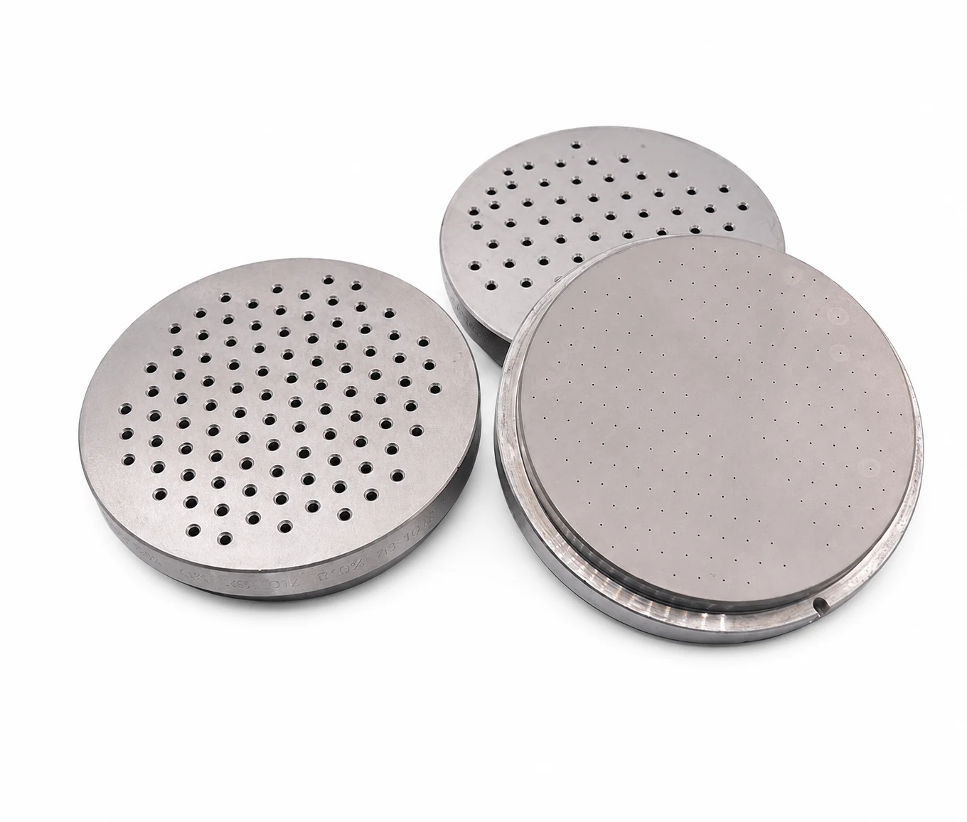
Spinneret plate; condition must be assessed against the approved inspection basis
Inspection Priority | Control Objective |
|---|---|
Capillary Size and Length | Verify tolerance, measurement method, sampling or 100% inspection and acceptance level. |
Profile Symmetry and Orientation | Control widths, radii, angles, segment spacing and rotational position for irregular holes. |
Entry and Transition | Check concentricity, surface condition and absence of machining damage or contamination. |
Exit Face Condition | Confirm clean edges without burrs, dents, scratches, deposits or polishing damage. |
Hole to Hole Consistency | Assess reproducibility across the active spinning area and identify plugged, worn or deformed capillaries. |
Tolerance Statement
Achievable tolerance depends on hole size, profile, length, material and inspection method.
The applicable grade must be stated on the approved drawing and quotation.
Materials and Construction
Metallurgy, Finish and Machine Interface Are Application Specific
Spinnerets may be produced in stainless steels or other corrosion and temperature resistant alloys. Selection must consider the spinning medium, thermal cycle, cleaning method, mechanical loading and required service life.
Design Element | Technical Review |
|---|---|
Base Material | Strength at operating temperature, corrosion compatibility, machinability and dimensional stability. |
Surface Condition | Specified working face, entry, transition and capillary finish; mirror, honed or other finish only where technically justified. |
Plate Form | Circular, annular, rectangular, segmental or custom geometry to the verified pack interface. |
Thickness and Support | Pressure loading, stiffness, seating and deflection risk across the active area. |
Sealing and Location | Outside diameter/profile, lands, shoulders, bolt pattern, keys, orientation and gasket interface. |
Cleaning Compatibility | Thermal, chemical, ultrasonic, hydrolytic or mechanical methods must not attack the alloy or precision surfaces. |
Traceability | Material identification, drawing revision, serial or batch marking and agreed inspection documentation. |
No Generic Substitution
A visually similar plate is not automatically interchangeable.
Verify the entire machine interface, active area, capillary geometry and pressure/temperature duty.
Project Confirmation
Availability of specific alloys, hardness, finish, treatments and certificates is confirmed in the technical commercial offer.
Filament and Yarn Quality
What Spinneret Condition Can Influence and What It Cannot Control Alone
Spinneret geometry and cleanliness directly influence individual flow passages. Final yarn properties remain system outcomes that also depend on polymer quality, filtration, metering, temperature, quench, spin finish, draw and heat treatment.
Quality Parameter | Spinneret Related Mechanism | Interpretation |
|---|---|---|
Linear Density – Decitex / Denier | Flow area and condition differences can change relative mass flow between holes. | Total Decitex / Denier is governed mainly by mass throughput and take up; compare both average and variation. |
Filament Evenness | Hole to hole dimensional variation, deposits or partial blockage can disturb filament consistency. | Monitor package to package and within package mass variation under stable process conditions. |
Cross Section and Profile Degree | Capillary outline and transition establish the nominal shape. | Final profile also depends on swell, drawdown, quench and solidification. |
Tenacity | Non uniform filaments or defects may contribute to weak filaments and breaks. | Tenacity is indirect: polymer molecular condition, orientation, crystallinity and draw history are decisive. |
Elongation | Flow or quench non uniformity can contribute to inconsistent draw response. | Elongation is indirect and must be assessed with the same draw and heat setting conditions. |
Breaks / Operability | Burrs, contamination, plugged holes or unstable profiles can disrupt jet formation. | Record break rate, drip, smoke, pressure trend and affected hole positions during trials. |
Appearance / Dye Uniformity | Cross section or mass flow variation can change optical response and downstream behaviour. | Correlate spinneret findings with dyeing, lustre, streaks and fabric inspection; other causes must also be excluded. |
Balance Claim
A precision spinneret supports uniformity and stable operation; it cannot compensate for degraded polymer, poor filtration, unstable metering, uneven quench or incorrect draw conditions.
Cleaning and Lifecycle
Cleaning Must Restore Flow without Changing the Capillary
Deposits and blocked passages should be removed by a validated method compatible with the polymer, alloy and surface finish. Aggressive cleaning can round edges, enlarge holes, scratch faces or leave residues.
01 ReceiveIdentify + Log | 02 Pre InspectDamage + Blockage | 03 CleanValidated Method | 04 InspectCapillary + Face | 05 ReleaseTraceable Status |
|---|
Lifecycle Control | Good Practice |
|---|---|
Incoming Condition | Record plate identity, drawing revision, service history, contamination and visible damage. |
Cleaning Route | Define thermal / chemical / ultrasonic / mechanical stages, limits, rinsing and drying for the actual polymer. |
Post Clean Inspection | Check every critical hole where required; verify face, transition, size / profile and residue status. |
Repair Decision | Approve re polishing, deblocking or capillary repair only against documented dimensional limits. |
Retirement Criteria | Remove plates with out of tolerance holes, cracks, excessive wear, distorted seating or unrecoverable damage. |
Storage and Handling | Protect precision faces and capillaries from impact, corrosion, dust and mixed identity. |
Trend the Asset
Link each spinneret identity to cleaning count, inspection findings, pressure behaviour, breaks and product results to support evidence based reuse limits.
Manufacturing & Quality Control
Release the Component Against Measurable Evidence
The manufacturing route depends on plate material, hole size, profile and quantity. What matters commercially is that the supplied component conforms to the approved drawing and agreed inspection plan.
01 ReviewDuty + Drawing | 02 MaterialGrade + Trace | 03 MachinePlate + Passages | 04 FinishFace + Capillary | 05 InspectDimensions + Condition | 06 ReleaseRecords + Packing |
|---|
Document / Control | Typical Content |
|---|---|
Approved Drawing | Revision, material, dimensions, datum system, hole profile, layout, tolerances and finish. |
Material Record | Grade and certificate level where specified in the order. |
Dimensional Report | Critical external dimensions, thickness, locating and sealing features. |
Capillary Inspection | Method, acceptance basis and results for size/profile, length, symmetry, orientation and condition. |
Visual / Face Inspection | Entry, exit, working faces, markings and absence of damage or contamination. |
Identification and Packing | Part number, drawing revision, lot/serial identity and protection of precision surfaces. |
Inspection Plan
Sampling, 100% inspection, calibrated equipment, measurement uncertainty and supplied reports should be agreed before manufacture not after delivery.
Commercial Clarity
Manufacturing origin, certifications, tolerance capability and documentation scope are confirmed in the quotation for each project.
Selection Data
A Complete Specification Connects Design to the Spinning Duty
Provide the following information with the approved drawing or verified sample. Missing process data should be resolved before capillary geometry or material is finalised.
No. | Information Required |
|---|---|
01 | Spinning route: melt, dry, wet or dry jet wet / air gap. |
02 | Polymer or solution, grade, additives, viscosity basis and operating temperature. |
03 | Product duty: POY, FDY, BCF, industrial yarn, staple, monofilament or speciality. |
04 | Total throughput, number of active packs and throughput per capillary. |
05 | Filament count, target Decitex / Denier and required cross-section/profile degree. |
06 | Capillary diameter / profile, length / L/D, entrance geometry and orientation. |
07 | Plate shape, outside dimensions, thickness, support and sealing interface. |
08 | Hole count, pitch, arrangement, active area and relationship to the quench field. |
09 | Material, hardness, surface finish, corrosion and cleaning requirements. |
10 | Approved drawing/sample, inspection plan, acceptance limits and documentation. |
Fastest Route to a Proposal
Send the current approved drawing, clear face and side photographs, polymer/process data, existing spinneret history, quality issue, cleaning method and expected annual quantity.
Design Outcome
Correct machine fit, defined capillary geometry, traceable inspection criteria and a controlled plant trial basis.
Plant Qualification
Approve the Spinneret Under Representative Operating Conditions
A controlled comparison with the current approved component is the best basis for routine supply. Keep polymer, filtration, metering, temperature, quench and downstream settings comparable wherever practical.
Trial Measurement | Record | Decision Value |
|---|---|---|
Fit And Sealing | Assembly, orientation, seating, leakage and removal condition. | Confirms machine interface and handling. |
Pressure And Throughput | Start up, steady state and trend at controlled temperature and polymer condition. | Checks flow resistance and operational stability. |
Filament Formation | Active holes, drip, smoke, profile stability, breaks and affected positions. | Identifies local capillary or process interaction. |
Linear Density / Evenness | Average dtex/denier, variation and package to package consistency. | Confirms mass flow and process repeatability. |
Tensile Properties | Breaking force/tenacity and elongation using the agreed method. | Confirms final product against the same downstream conditions. |
Cross Section / Appearance | Microscopy, profile degree, lustre, dyeing or fabric result where relevant. | Links geometry to the commercial product objective. |
Recommended Approval Sequence
01 BaselineApproved Control | 02 TrialMatched Conditions | 03 InspectProduct + Plate | 04 DecideEvidence + Limits |
|---|
Testing Basis
Agree conditioning, instruments, sample size and standards before the trial.
For yarn from packages, ISO 2060 covers linear density and ISO 2062 covers breaking force and elongation; application limits apply.
TEXFIL Application Support
From Application Data to Controlled Routine Supply
TEXFIL coordinates technical commercial review, drawing confirmation, sample qualification, trial planning and scheduled supply for synthetic fibre spinneret projects.
01 Application DataPolymer + Duty | 02 Drawing ReviewInterface + Holes | 03 Sample ApprovalInspection Basis | 04 Controlled TrialProcess + Quality | 05 Routine SupplyAgreed Controls |
|---|
Project Control | TEXFIL Coordination Basis |
|---|---|
Geometry and Fit | Approved drawing or verified sample, machine interface, sealing, orientation and active area. |
Capillary Design | Profile, diameter/slit width, length/L/D, entry transition, count, pitch and layout. |
Material and Finish | Selection against polymer/solution chemistry, temperature, pressure, cleaning and service life target. |
Verification | Agreed dimensional, visual and capillary inspection with defined acceptance criteria. |
Qualification | Plant trial plan covering fit, pressure, throughput, operability, filament geometry and product quality. |
Supply Documentation | Quotation, approved specification, inspection records, identification, packing and delivery schedule. |
Evidence Based Proposals
Correct machine fit, defined capillary geometry, traceable inspection criteria and a controlled plant trial basis.
Application Scope
Textile and industrial filament, staple fibre, monofilament, profiled and selected speciality fibre spinnerets.
Prepare Your Enquiry
What to Send Us.
Spinning route; polymer; pack drawing; hole count and profile; capillary dimensions; throughput per hole; filament specification; inspection requirements.
Discuss this product